Improved Gotek Floppy Emulator
Motivation
I enjoy collecting older computers, particularly ones from the mid-to-late 1970s through the early 1980s that run CP/M. Machines from this period commonly have 8" or 5.25" floppy drives. Finding working 8" or 5.25" floppy drives is becoming increasingly difficult. So is finding media.
To address this problem for his Atari ST, Jean-Fancois Del Niro created HxC2001, which is a hardware-based floppy drive emulator. Over time support for different drive types and floppy image formats has been added. HxC2001 is quite capable, but can also be quite expensive per drive (upwards of $100US per unit).
Recently, GOTEK has created a less expensive but less capable unit sold on eBay and Amazon. It works, but the firmware is much more limited and the software to install images is less than user-friendly. The interface it presents to the computer is IBM-compatible only. This is a problem for using it in older computers that expect a Shugart-style floppy interface unless you’re willing to do some custom cabling. Even then, compatibility is not perfect.
The good news is that the HxC2001 project has ported their excellent firmware to the GOTEK floppy emulator. With a few simple steps, you can convert a very inexpensive (<$30US) GOTEK emulator into a retro-floppy emulator with excellent compatibility for older machines.
The HxC2001 website provides fairly clear instructions on how to upgrade a GOTEK floppy drive emulator to use HxC2001 firmware. To illustrate the steps for someone trying this for the first time (and to add a few tips and suggestions), I’ve put together this step-by-step guide. You can find the “official” instructions here.
Parts Needed
- (1) GOTEK Floppy Drive Emulator (eBay search here)
- (1) USB-to-serial adapter with 3.3V output (eBay search here)
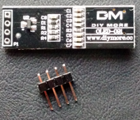
- (1) 5-pin header strip (eBay search here)
- (1) 4-pin header strip (eBay search here)
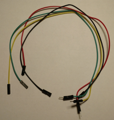
- (4) “Dupont” leads (eBay search here)
- (1) 1 header jumper (you can borrow this from one of the other headers on the GOTEK during programming)
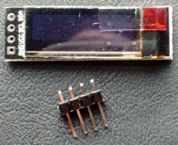
- (1) 0.91" OLED 128x32 Display (optional) (eBay search here)
Even if you don’t have any of these on hand, if you shop carefully, you can get the parts for $35US or less. Here are some pictures of the parts I used:
Upgrade Process
Purchase an STM32 Bootloader from the HxC2001 project
You can purchase the bootloader here. The HxC2001 firmware itself is free, but to install it on non-HxC2001 hardware, it requires a special bootloader. For STM32 based floppy emulators like the GOTEK, there is a nominal charge (about $12US at the time of this writing) for the new bootloader. The bootloader enables the GOTEK emulator to load the official HxC2001 firmware from a USB stick. (Note: It also enables future upgrades by placing new firmware on a USB stick, inserting the stick, and powering on the GOTEK with both buttons pressed. You only have to buy the bootloader for the GOTEK once. Once you complete the purchase, you will receive an email that contains login credentials to use with the Online Bootloader Flasher utility. That utility can be downloaded here.
Connect GOTEK to USB Adapter
To flash the new HxC2001 firmware onto the STM32 processor in the GOTEK, you will need to connect a PC running Windows to the serial port on the GOTEK emulator. Unfortunately, the Online Bootloader Flasher utility only runs under Microsoft Windows. However - if you are a Linux user (like me), it runs just fine under Windows inside of VirtualBox. NOTE: I have not tried running it under WINE directly. If anyone has, please let me know so I can add that information here.
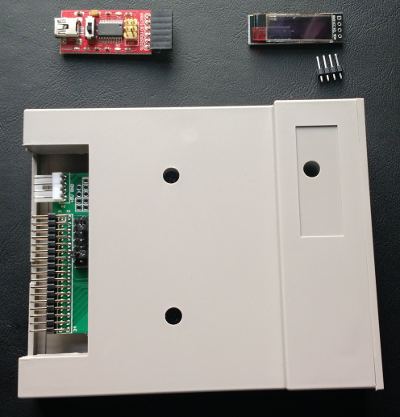
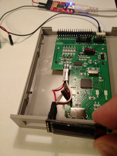
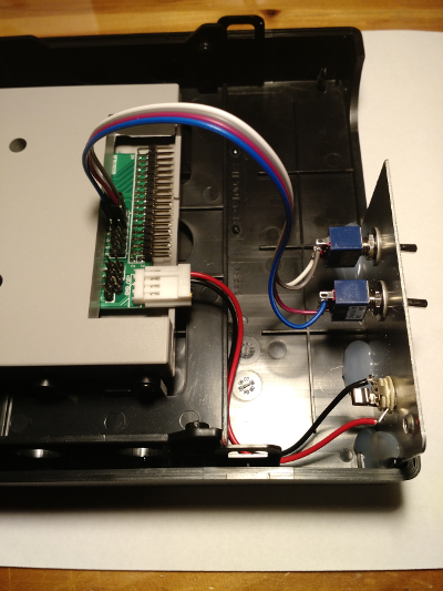
Here is what the inside of the GOTEK looks like from the factory:
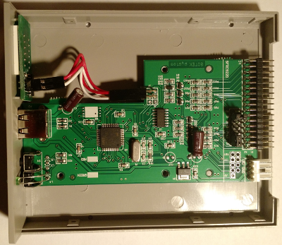
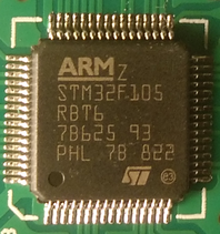
Looking at the image above, to the left, from top to bottom, you can see the 3 digit LED display, USB port, floppy image selection buttons (lower left), and the activity LED (green). On the right-hand side, you will see the 34 pin floppy connector, with the device select header behind it (more on that later), the power connector, and the serial port/BOOT0 header just behind it. For the curious, the GOTEK uses the STM32F105:
Before proceeding any further, connect your USB to serial adapter to the Windows PC, and go through any necessary driver installation process. You can verify that it is operating correctly by downloading and installing PuTTY or TeraTerm, bridging RX and TX on the USB adapter, and verifying that you see the characters you type in the terminal.
IMPORTANT: Be sure you have an adapter that supports 3.3V signaling. You must set it to 3.3V signaling, or you risk damaging the STM32 processor in the GOTEK.
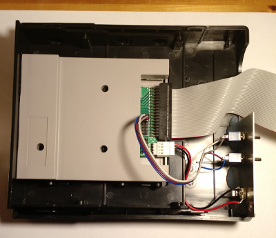
There are several tutorials on YouTube and the web that have you shove Duport wire ends (or even paper clips!) into the PCB of the GOTEK. For a much smoother experience (with no retries), I would strongly recommend soldering in pin headers like this:
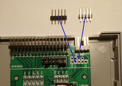
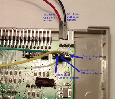
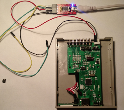
Once you have soldered in the pin headers, you will need to connect the USB to serial adapter to the GOTEK:
- Bridge J3 (BOOT0) with VCC3V (right next to it)
- Connect the USB adapter RX to TX on the GOTEK (3rd in from edge)
- Connect the USB adapter TX to RX on the GOTEK (4th in from edge)
- Connect GND from the USB adapter to one of the center 2 pins of the power connector on the GOTEK
- Connect 5V from the USB adapter to the 5V pin (innermost) of the power connector.
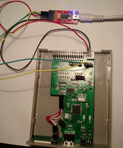
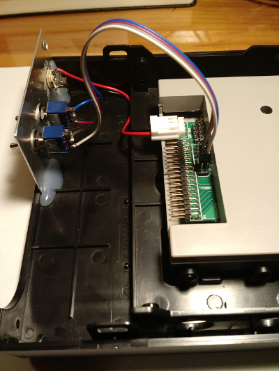
When you’re done, it will look something like this:
Program the new Bootloader.
Start the Online Bootloader Flasher, and enter the IP address and credentials you received via email:
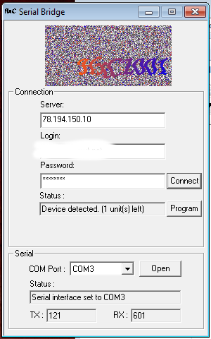
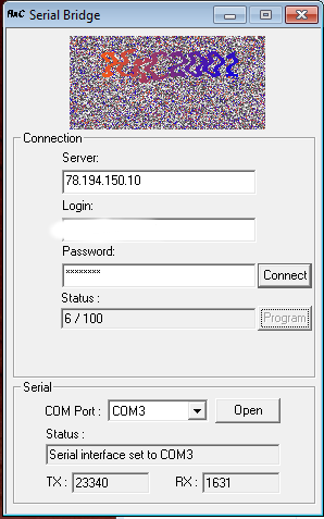
After a short time, the Online Bootloader Flasher should detect the GOTEK, and begin to upload the new Bootloader. If you don’t get a Device Detected message, check that you have not reversed RX and TX. You may also want to reset the GOTEK by bridging RST to GND (innermost two pins on programming header). Depending on your internet connection speed, this may take a few minutes:
Once Bootloader programming is complete, you should get a “LDR” message on the 3 digit LED display:
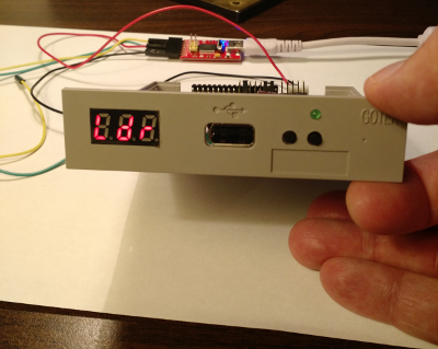
If you have made it this far, congratulations! The “hard” part is done!
Loading the HxC2001 Firmware.
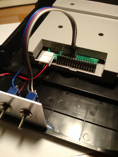
Disconnect the RX and TX leads from the programming header, and remove the jumper on BOOT0, but leave the 5V and GND leads connected:
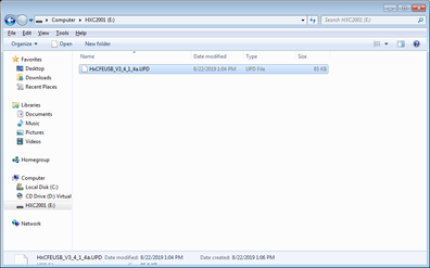
Copy the latest HxC2001 firmware onto a USB stick (preferably all by itself):
Place the USB stick into the GOTEK, and after some activity on the LED display, it should look like this:
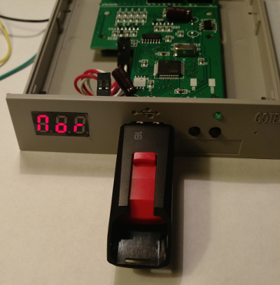
The activity was the firmware being stored by the Bootloader. The “NOR” message afterward indicates that there are no floppy images on the USB stick (which is expected at this point). The GOTEK is now ready to use! To enhance your experience, I would recommend that you follow the next (optional) step, and install an OLED display in place of the 3 digit LED display. You can use the LED display, but keeping a list of image numbers handy can be a bit annoying. By installing the OLED display, you get to see the selected floppy image by name, and you also get a very nice track number display that shows you what the floppy emulator is doing. It is well worth the extra few dollars and 15 minutes it takes to install.
Install on OLED display (optional)
IMPORTANT: Disconnect the 5V lead from the power connector before completing this step! Next, disconnect the 4 leads from the back of the LED display, and remove the LED display from the case. Using the following two images as a guide, connect VCC (3.3V), GND, SDA, and SCL between the GOTEK mainboard and the OLED display:
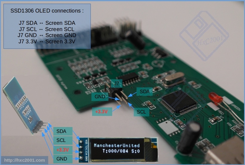
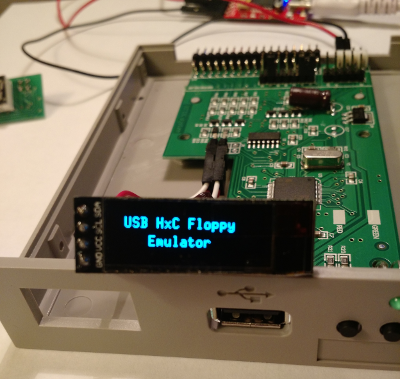
Reconnect the 5V power lead, and you should see something like this:
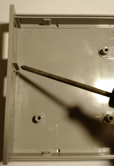
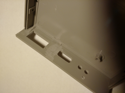
To fit the OLED display into the GOTEK case, you will need to make a couple of small modifications. First, you will need to grind away two ridges in the lower case half:
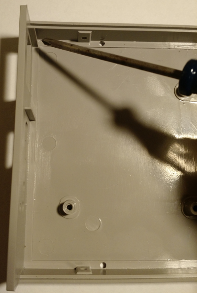
After:
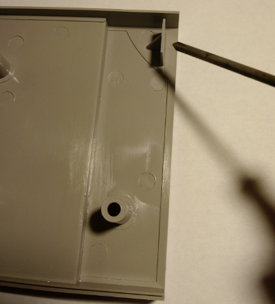
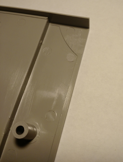
You will also need to grind off a tab in the upper case half (before and after):
At this point, the OLED display can be put in place (I used hot glue), and the GOTEK case can be screwed back together. If you are not mounting the GOTEK directly in the computer, keep reading for notes on how I mounted mine in a way that can be moved from machine to machine.
Mounting the GOTEK
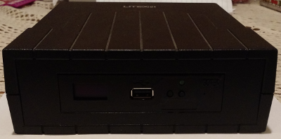
I had plans to use my GOTEK with several different machines. To do that, it needed to be mounted in a secure external case and connected to its’ own 5V power supply. In my junk pile, I had an old USB CD-RW drive in an external case. The drive had died long ago, but the switching power supply was still good. You may have something similar in your junk pile, or you may find something old, broken and cheap on eBay. In my case, the first step in mounting the GOTEK into the case was placing it in a 3.5" to 5.25" drive bay adapter:
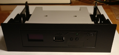
The 3.5" to 5.25" adapter was an eBay purchase. You probably noticed that the GOTEK is now black, not beige. My original plan for mounting the GOTEK didn’t work out, so to match case colors with the old CD-RW drive case, I sprayed the GOTEK black.
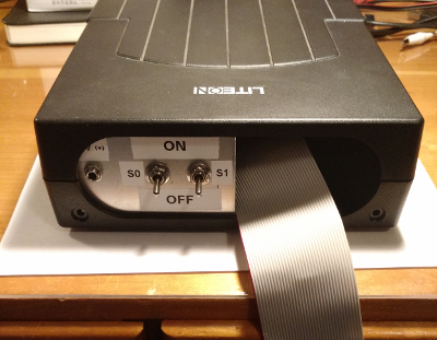
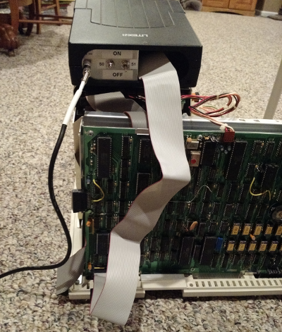
The GOTEK is much shorter than the CD-RW drive that was original to the case. That means that changing drive selector options (S0=Drive 0, S1=Drive 1) right behind the 34 pin floppy cable would require re-opening the case. Also, changing floppy cables would be difficult without re-opening the case as well. I decided to mount two SPST switches and the power connector to the rear of the case, using a spare piece of aluminum plate that I had from another enclosure. The switches allow me to short the S0 and S1 drive selection jumpers without opening the case. I have decided to leave the floppy cable connected to the GOTEK, and thread it through the opening in the read of the case. The floppy cable is a classic PC floppy cable, with both 34 pin female IDC connectors, as well as 34 position female card edge connectors. To keep the true sense of S0 and S1 (as Drive 0 and Drive 1) selectors, I cut off the last 8 inches of the cable, which included “the twist”.
Another nice feature of HxC2001 firmware is that you can customize it to suit your hardware, including removing features that you don’t need. I did exactly that, removing support for the LED display and optional 3rd selector button (the GOTEK only has 2). If you would rather not go through the customization process, you are welcome to download my customized version here. You will need to place it on a USB stick, insert the stick into the GOTEK, and power it on with both buttons pressed.
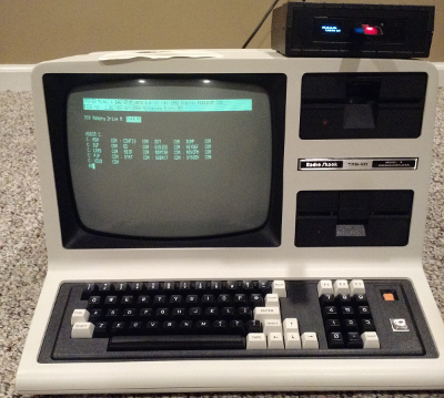
Using the GOTEK with a TRS-80 Model 4
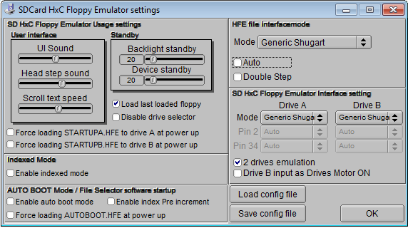
The TRS-80 Model 4 uses two internal drives with a Shugart interface. This interface is slightly different from a standard IBM-PC compatible interface (read more about this here. The HxC2001 can emulate either interface. Before connecting the GOTEK to a TRS-80 Model 4, you need to set up a configuration file that tells the GOTEK to emulate a Shugart drive. The HxC2001 project has a nice configuration utility that allows you to set that up. I chose the SD configuration option since its’ hardware is more closely related to the GOTEK:
If you want to use my configuration file, grab it here. It should be placed in the root directory of the USB stick. The next step is to grab some TRS-80 floppy images from the web. Here is a short list of places that you can find TRS-80 software disk images:
- https://www.willus.com/trs80/
- http://www.classiccmp.org/cpmarchives/trs80.php
- http://www.manmrk.net/tutorials/TRS80
- http://www.tandytrs-80.com/trs80/downloads.htm
- http://www.tim-mann.org/misosys.html
IMPORTANT: Once you’ve downloaded DSK or DMK files, you will need to use the Floppy Drive Emulator software (the same software you used to create the HxC2001 configuration file) to load each image, then save them as HFE format files. The HxC2001 does not directly support TRS-80 floppy images, but the software allows you to change it into a format that works with the HxC2001 firmware.
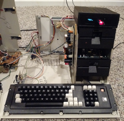
Connecting GOTEK and TRS-80 Model 4
To connect the GOTEK to the Model 4 as drive :2 or :3 (external drives 3 and 4), you will need a standard IBM-PC floppy cable that supports 5.25" drives and has the 34 pin female card-edge connector. Note: Some 5.25" floppy connectors have a “key” that goes into a slot on the floppy drive control board. You will need to either find a floppy cable that does not have that key or file/clip that key out. The external floppy connector on the bottom of the Model 4 does not have a corresponding slot for the key and the cable will not fit if it is keyed. Once you have the cable prepared, connect the floppy controller end (the isolated 34 pin IDC female connector on the very end by itself) to the GOTEK. Be sure that the red stripe is at pin #1 on the GOTEK. See construction pictures above if you are unsure which way to connect the cable. Next, connect the first 5.25" female floppy connector to the floppy port on the bottom of the Model 4:
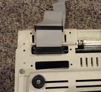
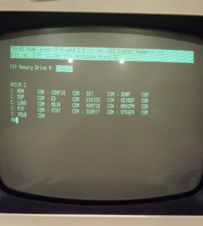
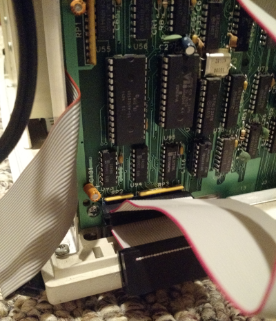
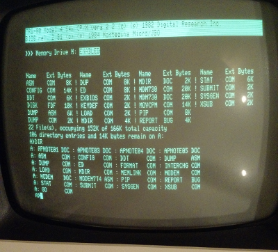
Notice that the red line (pin 1 marker) is towards the outside of the Model 4. Once it’s connected, boot into your favorite TRS-80 operating system and try to access the GOTEK as a drive. In the photos below, I’ve booted Montezuma Micro’s CP/M (BIOS 2.31), used the CONFIG utility to define drives 2 and 3 as CP/M system drives, and accessed the directory of C:
NEWDOS and TRS-DOS users will need to use the SYSTEM command to enable drives 2 and 3 before access to the GOTEK will work. But will it boot from the GOTEK? You bet! Just connect the GOTEK to the internal floppy connector on the motherboard, and away you go! Be sure to connect pin 1 (red line) of the floppy cable to pin 1 (toward outside edge) on the motherboard:
Here is CP/M booting directly from the floppy image, followed by switching floppy images (using the front buttons) and doing another directory:
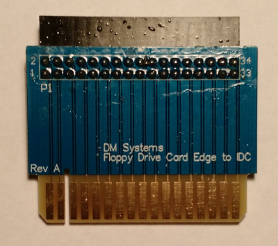
If you wanted to permanently mount the GOTEK in your Model 4, you could swap out the Model 4 floppy cable for an IBM-PC floppy cable. Just be sure to observe the pin 1 indicators, don’t use the part of the cable after the twist (or maybe just cut that part off) and you should be set. As another option, I found these on eBay, which allow connecting the GOTEK directly to the original TRS-80 floppy cable:
More systems to be added later… stay tuned…