Programmable Current Sink
Motivation
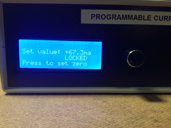
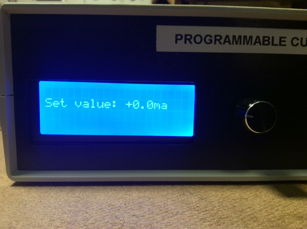
Recently, I began a project to build a (reasonably) accurate 3-axis magnetometer. One of the challenges in building a magnetometer is calibrating it with a known magnetic field. Creating a known magnetic field requires using a calibration coil with a known current flowing through it. If you want to make multiple (and consistent) measurements, it is very convenient to have the current under computer control…and that is where the Programmable Current Sink (PCS) got its’ start. The PCS allows computer control of current with 0.1ma resolution across a range of 0.1ma to 100ma, or 1ma resolution from 5ma to 1000ma. The current values are very stable, and repeatable.
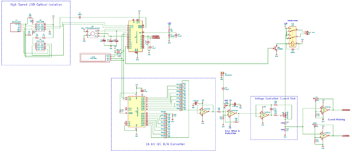
The following schematic shows the general structure of the PCS (click here for a much better PDF version):
Circuit Description
Starting in the upper left of the drawing, the schematic shows a USB optical isolation circuit. For the PCS I used a USB Type B Female Adapter (greater strength in the connector). You can see the adapter on Amazon here. One of the first stability challenges I ran in to was that “ground” differs from device to device, especially if your laptop does not use a three-prong power supply. Plugging the laptop in caused current to flow in the ground rail of the PCS, which threw off current measurements in the low range (and honestly had me pulling my hair out for a while trying to diagnose the performance problems when the laptop was connected.) The solution to the “ground current” issue was to isolate the USB connection optically. I tried several different opto-isolators, but every one I tried was too slow to support a baud rate above 9600 reliably. Some googling located the HCPL-2430, which is a high speed “logic gate optocoupler.” They operate at over 20MBd, and easily support the 57600 baud I wanted to use for the control interface. C1 acts as a “reset pulse” generator triggered from the DTR line of the USB interface. That allows me to use AVRDUDE to easily re-flash updated code onto the Arduino Nano, but still provides galvanic isolation.
Following the USB interface is the logic/control section. The control section is built from an Arduino Nano, KY-040 rotary encoder, and 20x4 line LCD interface. The rotary encoder and LCD provide an interface to control the unit if a laptop isn’t handy, but aren’t needed to operate the PCS. Capacitors C3-C5 are used for debouncing signals from the rotary encoder. D1 provides a stable voltage reference for the A/D converter in the Nano. Analog channel 0 measures the low control range (0.1ma to 100ma), and channel 1 measures the high control range (5ma - 1000ma). Capacitors C6 and C7 provide some noise filtering for the output from the current sampling circuit (U4 & U9). D12 controls a DPDT relay in the upper right, allowing the the current direction to be switched under program control.
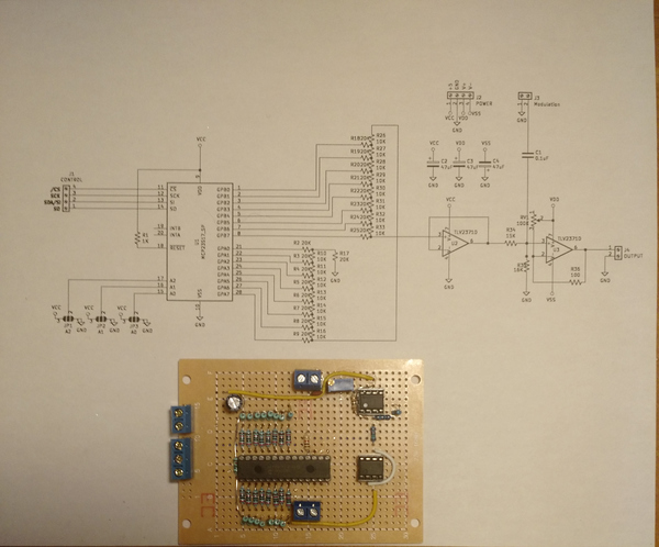
Right below the logic/control section is the D/A converter. There are 16 bit D/A modules available, but they can be quite expensive. I used an MCP23017 I2C GPIO chip, combined with a hand-matched 1% R-2R resistor network (R10-R25 & R29-50), to achieve the same result. The D/A converter is used to develop a drive voltage to control a voltage-controlled current sink made from U8 and Q2. U6 acts as an output buffer for the D/A converter and feeds U7. U7 provides negative gain (attenuation to reduce the 0.005V - 4.95V output of the D/A to a more useful range) along with a negative offset. RV2 serves two purposes: it allows the drive offset to be adjusted so that the input to U8 is 0V (or slightly negative) when the D/A is set to zero; it also ensures that the voltage-controlled current sink it pulled off ‘hard’ when at zero. C8 allows “modulation” to be added with the current control voltage. This will be useful for testing the dynamic response of sensors.
Following the drive offset & modulation section is the voltage-controlled current sink (or source, depending on which convention you want to follow.) The current through the coil connected to the PCS is equal to the current through R40 and R45. R40 and R45 together act as a “current sense” resistor for the feedback loop made from R23. Voltage changes to pin 3 of U8 cause the output to swing the drive to Q2, raising or lowering the current through R40 and R45, and matching the voltage of pin 3 on pin 2. C12 increases stability.
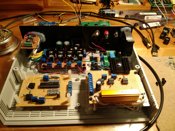
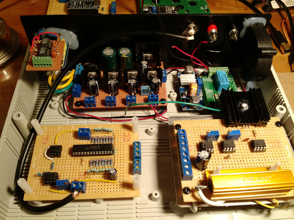
Large power resistors were used for R40 and R45 to minimize the effect of heating (see following photos):
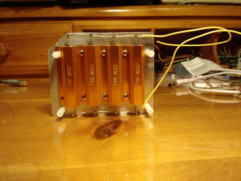
R45 is a composite resistor made from 4 100W 2ohm resistors. In parallel, that gives 0.5ohms with a dissipation capacity of 400W. The mass and dissipation of R45 are orders of magnitude more than is needed for the current the unit can support, but are necessary to minimize the change in value due to heating. This gives greater stability and longer run times before the calibration begins to drift.
U4 and U5 sample the voltage across R45, and provide feedback for the logic and control section.
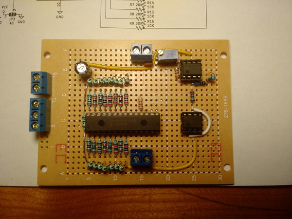
The first module I built was the D/A module:
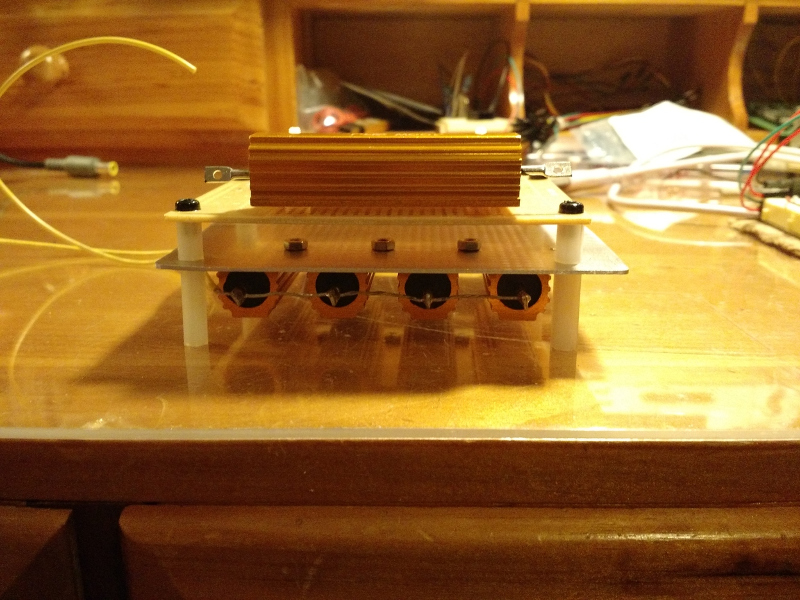
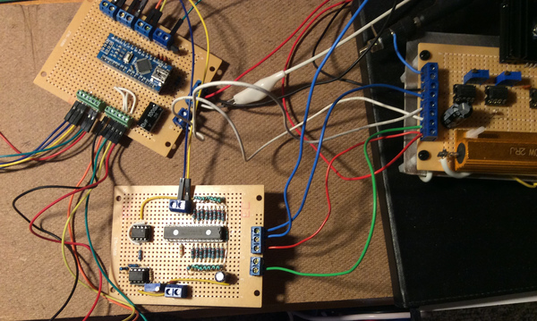
Next came the current sink module and the metering, followed by the logic and control module. Then it was time for a final bench test before pulling it all together:
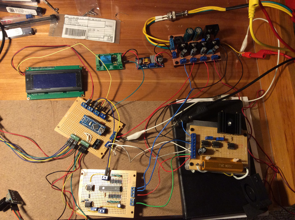
In this next picture, the relay module used for switching current polarity is visible (RL1). There is also a small power supply just for the relay. Placing the relay on its own power supply prevented variations in current between forward and reverse polarity. Energizing the relay drew enough current to create a slight variation in output current for the unit. In retrospect, I believe raising the values of R40 and R45 will eliminate that sensitivity.
Next came a test fit into the case I was hoping to use…
.. followed by the actual construction:
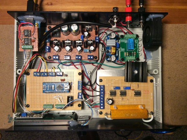
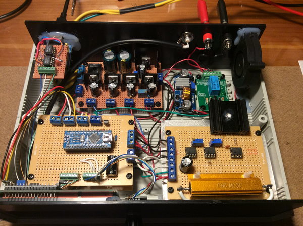
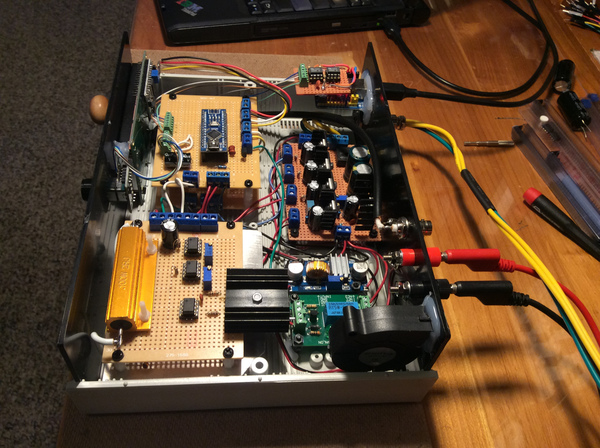
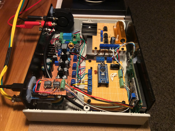
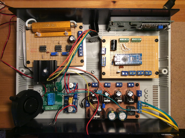
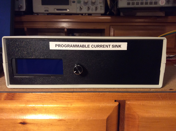
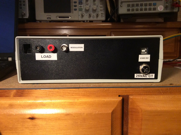
The fan was added to pull lots of air past Q2 and R45. The linear power supply (+5V, -5V, +18V) is at the rear center of the case. The 4th channel is an adjustable output to tweak the speed of the fan. The power supply is fed by 25VAC, which I also use to power a number of different home-brew devices on my bench. You will have to excuse the cutout for the LCD. I measured three times, marked it off with tape, but still managed to make a mistake. Oh well. Maybe I’ll 3D print a new front panel someday. Here is the finished unit, ready for final calibration:
Calibration
I used a lbratory calibrated HP 3478A multimeter in series with the load coil to calibrate the PCS. Hand matching resistors can get you very, very close. To adjust for any variance in the resistors that make up the D/A R-2R resistor ladder, the firmware separates each range (0.1ma - 100ma, 5ma - 1000ma) into a series of 20 segments. By slightly tweaking the endpoints of each segment, it is possible to reduce errors across the entire range to very low values. TIP: Another method of calibration could measure the current output via the voltage across a precision resistor.
Firmware
The firmware for the PCS is under active development (and cleanup). Once the control algorithm has been fine-tuned, I will post a copy here. The serial interface is straight-forward, with commands for setting the range, current value, and polarity:
Programmable Current Sink Apr 16 2020
Measuring zero on A/D channels...done.
Press 'C' for Calibration Mode, 'D' for Diagnostics, or wait for Boot: 0

Ready.
?
R[m|a] - Set range to 0-100ma, 5-1000ma
P[+|-] - Set output polarity to + or -
Snnnnn - Set output to nnnnn ma
G      - Set state
M[+|-] - Set modulation mode on/off
Ready.
rm
Range: 100ma
Ready.
p+
Polarity: Forward
Ready.
S500
LOCKED
Ready.
G
Range: MA
Set: +500
Modulation: Off
Ready.
S0
Ready.