Vlf Reception System
Important Note
I am currently consolidating a number of web pages from my old website into this single-source post. Please be aware that a number of significant updates are in progress on this page, and things may be missing for the time being.
VLF E-Field Receiver
This page is a summary of my current E-field receiving system, and is constantly being updated as I try different experiments to improve the system. I have included notes from previous versions of my reception system, in the hope that the lessons learned will help anyone trying variations of this system.
You can listen to my current receiver while you read:
Receiver Design and Theory Of Operation
RX-6 gets its name from being the 6th major revision of what amounts to an e-field probe feeding a very low noise op-amp. In reality, there were many more than 6 variations, as I made changes in design and layout, and observed the effects.
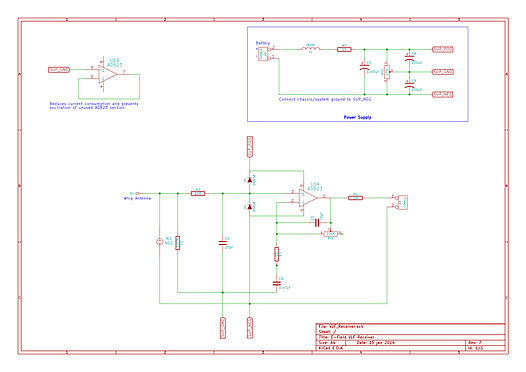
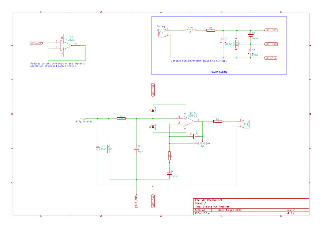
The receiver front end amounts to an e-field probe feeding a very low noise op-amp:
Click here for a larger version.
Circuit operation (as I see it, anyway): R1 acts as a bias R for the input of U1, an AD823. R2 and C1 form a low pass filter with a cutoff of approximately 630kHz. R2 and C1 also slow incoming transients (to a degree) to allow switching diodes D1 and D2 to clamp excessive input to either the V+ or V- rails. NE2 rounds out the input protection and provides a flash over point between the whip antenna and system ground. U1 is a very low noise op amp, configured as an adjustable gain non-inverting amplifier. First stage gain levels are set between 1 and 100 via RV1 and R3. C2 forces U1 to also act as a high pass filter, with a cutoff frequency around 100Hz. C3 provides high frequency roll-off to help with broadcast band (AM) interference. R4 and C4 form and additional low pass filter with a cutoff of approximately 160kHz. R5 acts as a load for the AD823 to help with oscillation, as the input to the line driver stage (U2, OP27) doesn’t present much of load. U2 is a low noise op amp with a low input impedance configured as a non-inverting amplifier with a gain of 2, as well as a second stage of high pass filtering with a cut off frequency of about 100Hz. U2 also acts as a line driver stage for the receiver, and is coupled into a 1:1 matching transformer via C7 and R9.
The unused section of U1 is configured as a voltage follower, with its input pinned to the virtual ground between V+ and V-. This seems to reduce the current consumption of the AD823, and also prevents the unused section from oscillating.
The power supply (shown in the larger graphic) provides the split power supply necessary for the receiver. The current draw on the virtual ground rail (SUP_GND) is minimal, so a simple passive voltage divider will work. L1 and R7 help to decouple the 4 foot cable run from the supply battery on the ground. Despite the good power supply noise rejection of the AD823, leaving them out increases interference in the receiver.
The gain was set at 70 in my implementation. The overall receiver as drawn is capable of a gain of 200.
The input low pass R2/C1, roll-off cap C3, and low pass R4/C4 were all necessary to prevent a local (10 miles) 50kW AM station from injecting all kinds of intermod into the VLF signal.
The AD823 has a drive capability of 15ma, and is rated for a 500pF load. If you decide to use cable rather than an optical link, note that run into a long run of twisted pair cabling with its high capacitive load, the signal can become quite distorted. If you examine the parameters for common coax or twisted pair cable, you will see that the total capacitive load of even modest cable runs in in the 1000s of pf. You may want to add another stage with an OP27, as it is somewhat beefier than the AD823, able to source around 20ma and drive capacitive loads up to 2000pf. It is better suited for driving a longer signal line.
Design tip: If you are building an op amp based receiver like this one, be sure to check the voltage and current noise parameters of the op amp you intend to use. Using these you can infer the ’natural’ source impedance that the op amp expects. In an e-field probe, low input current noise and high impedance are important.
Construction Tips
If you build one, I recommend trying the RX-6 out on a breadboard. The RX-6 is not a high frequency design, so in general layout is not that important - to a point. The gain of the receiver is not insignificant, and coupled with the high impedance input stage it can tend to oscillate if you don’t take some care in construction and signal routing. The first few versions were on a small breadboard with a very messy layout (a result of many revisions and experiments.) Cleaning up the layout and spacing things on a larger breadboard has completely eliminated the early oscillation problems.
My long term goal is to make a PC board for this receiver, which should be relatively painless with something like KiCAD or gEDA
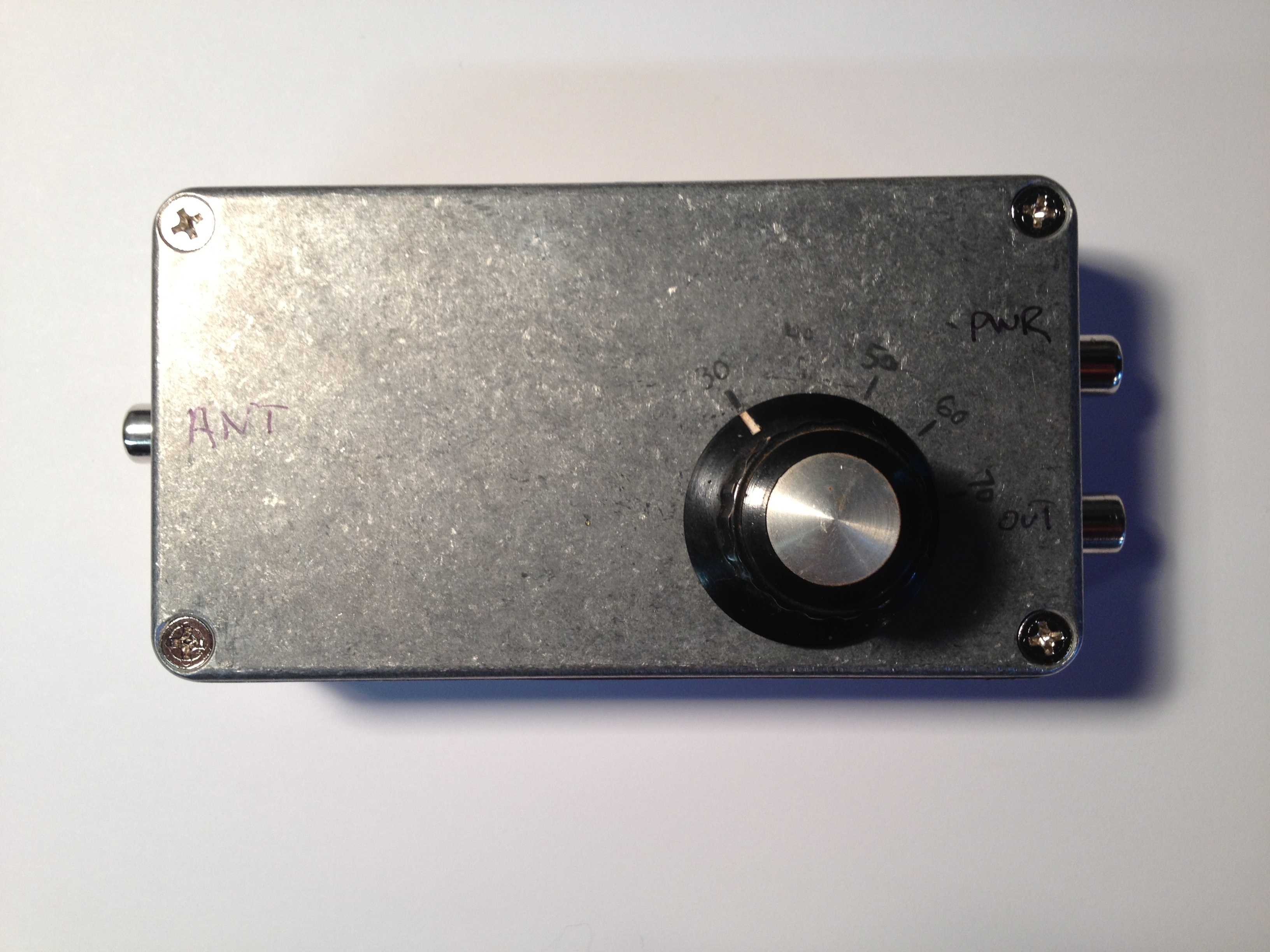
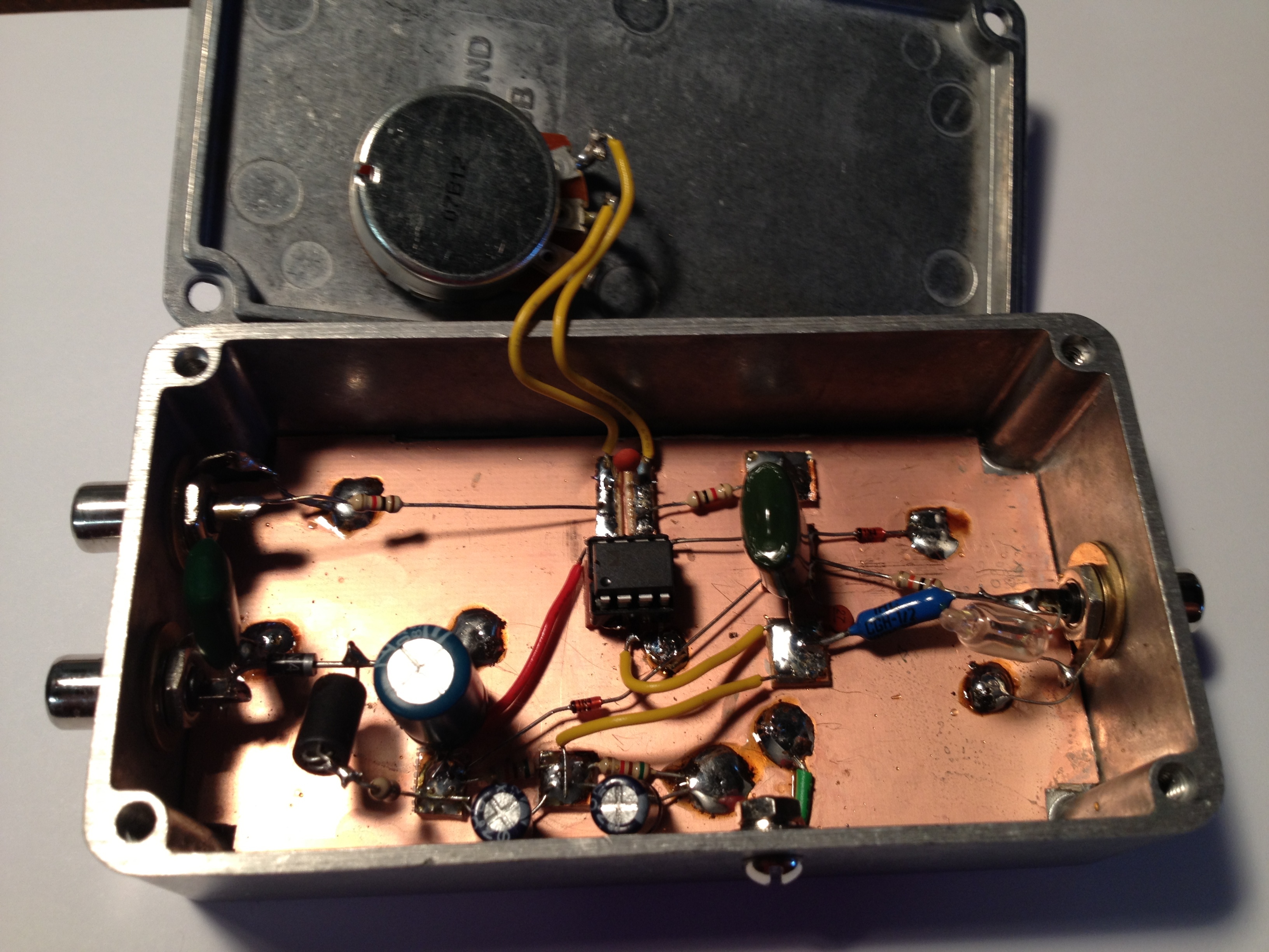
For now, I’m using manhattan style construction in a Hammond aluminimum enclosure:
Receiver Performance
The noise floor of RX6 is below the VLF spectrum noise floor, allowing relatively clean reception. Overall, the dynamic range is also quite good.
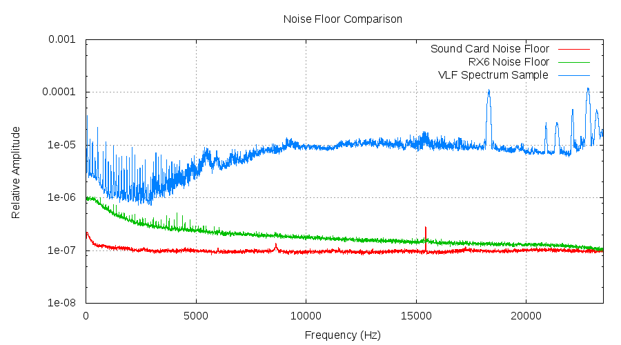
In the chart above, the red line represents the noise floor of the PC sound card used to interface with the RX-6. The green line shows the noise floor of the RX6 itself, with no antenna connected and a small capacitive shunt across the antenna terminals. The blue line shows a snapshot of the local VLF spectrum from 0-24khz. As you can see, the noise floor of the receiver is below that of the VLF spectrum we’re trying to receive.
The upward swing of the RX-6 noise curve below 5kHz may be able to be improved by raising the value of the bias resistor R1. It’s on the list to try, anyway.
The slight upward tilt of the VLF spectrum above 23kHz in this graph was an artifact of the sound card I was using at the time (Sound Blaster!), and not from the receiver itself.
My Reception Environment
The part of central Virginia in which I live is located in the foothills between Lynchburg and the Blue Ridge Mountian Range. The area is mostly forest and farmland, woven with many streams, rivers and several large lakes. It is dotted with low density housing and sparsely placed small cities. It has the occasional high voltage power line, but most of the power lines follow streets and highways. The soil is predominately a red clay, with granite, limestone and volcanic formations underneath.
My current home is in a development with underground power lines, with above ground transformers set on pads at ground level. The nearest above ground power lines are about 1000ft to my north, behind a thick patch of forest on the north part of our property.
How To Choose A Receiver Site
The AC mains hum, it’s harmonics, and interference from other local sources can set up standing patterns with ’local’ maxima and minima. Through careful study and observation, you can select a location that minimizes (relatively speaking) that interference.
It may seem like an obvious statement, but taking the time and carefully selecting a location for your VLF receiver is important. In my experience, just a matter of a few feet can make a 20dB difference in hum levels.
Take the time to build or borrow a VLF receiver, and survey your area to select the best spot. You will save yourself a good deal of frustration later.
I found a location to the north east of the house, which places the house between the receiver and the nearest above ground transformer. This particular receiver site is good enough, in fact, to be able to listen to the VLF band using a portable receiver without a filter! I was quite amazed, given my prior experiences with VLF reception at home, to be able to stand there and listen to tweaks and sferics without fatigue from AC mains buzz.
Some tips:
- Build a ‘mobile’ receiver, constructed in a case that lets you mount a whip, and a ground spike (like a tent stake or long shaft screwdriver.) It makes taking fixed observations much easier.
- If you have a netbook or laptop, don’t select candidate spots by ear only. While it may sound like you have found a local minima just by walking around, there are other sources of interference that are at the edge of your hearing that will only show up on a spectrogram. Wolf’s SpectrumLab running on a netbook is excellent for this purpose.
- Isolate the rx from your laptop with a 1:1 audio transformer, and several meters of wire (at a minimum). This should keep a lot of the noise generated by the laptop from bleeding into the signal.
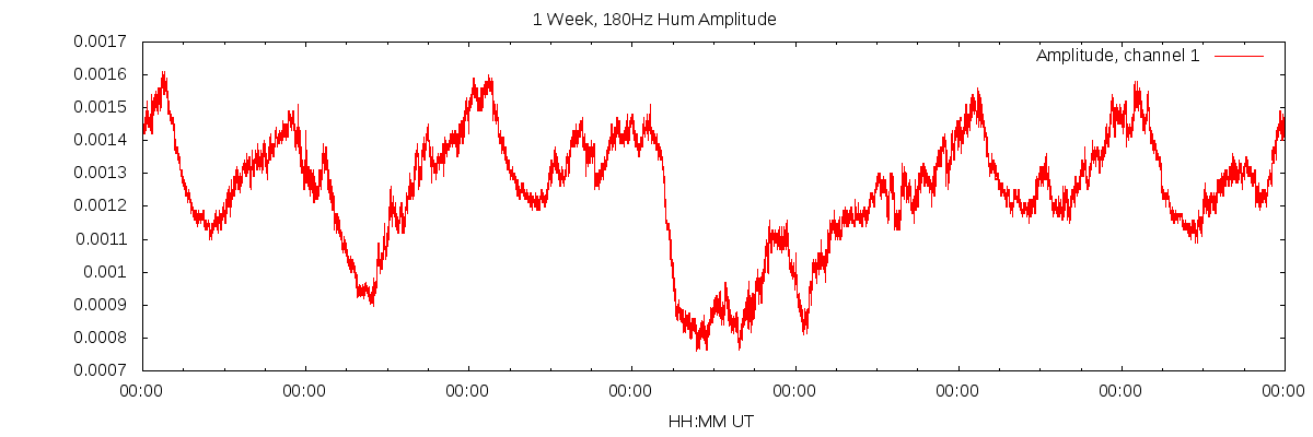
- Take samples for each location at multiple times of day (and night.) Hum varies quite a bit, depending on the weather, neighbors and a dozen other factors. A spot that sounds good now, may end up being awful the rest of the time. As an example, here is how the AC mains 3rd harmonic varied with time at my location:
- Take detailed notes. Save spectrum samples with time and location information. You will be glad you did when you go back to analyze your options or get a second opinion.
- If you are setting up an e-field receiver like this one, avoid the obvious, like nearby transformers, power lines and your home. Also avoid: trees, metal fences, chicken wire around the garden, clothes lines with metal cores, drainage grates, metal lawn furniture, sheds, outdoor cabling and lighting fixtures. Anything and everything metal. In my experience, all of these enhanced mains interference.
Getting The Signal Somewhere Useful
Getting the VLF signalfrom an RX-6 to the PCs I’m using for processing the signal proved to be one of the single biggest challenges I faced. While it sounds relatively straight forward, like stringing some coax or twisted pair from point A to point B, there are a number of issues that adversely effect the quality of the signal and the performance of the receiver. If you are going to try a wired connection (rather than the optical system mentioned in the next section), here are some tips to help:
Tip 1: Watch the ground potential
A difference in ground potential between your receiver and where you process the signal. Try this experiment: Place a ground rod in the spot you’ve selected for your receiver, and add a run of hookup wire. Use this to measure the difference in potential between your domestic ground (which feeds your PC) and the earth. If you see a 10mV or 100mV difference, you’ll probably be fine with transformer isolation. However, in my case, there was over 1V difference, in the form of a nasty, spiky triangular waveform. After some investigation (turning off and disconnecting different loads in my home, checking ground resistance for my breaker panel, etc.) I came to a preliminary theory that the differential voltage probably came from the placement and grounding of the in-ground transformers in our old neighborhood, causing ground currents. The best above ground e-field “hum minimum” on my property was on the general axis between two of the transformers - which places the ground rod along a ground current path.
Tip 2: Avoid long cable runs
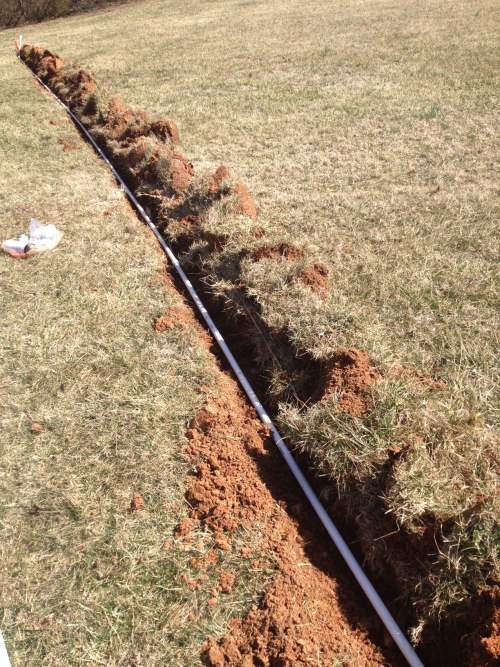
Long cables, even on/in the ground, can act as a very nice antenna for interference to enter your receiver. Be careful where you run the signal line for your receiver - avoid running parallel to power lines (inside and outside), near signal lines for TV antennas/satellite dishes, in-ground accent lighting, etc. Unless trees or other obstacles prevent it, shorter direct runs are best. I have had good success burying my signal cable 1-2 inches underground.
Tip 3: Isolation Transformers
Even if you utilize 1:1 transformers on your signal line to provide ‘galvanic isolation’, you still aren’t truly ‘isolated’. Why? Every transformer has a (usually) small but finite capacitance between the primary and secondary windings. That capacitance acts as a path for AC signals. In this case, it can act as a path for that nasty 1V sawtooth. I ended up using a series of 3 transformers in my signal line, and I am contemplating adding a fourth. Fortunately, adding the transformers didn’t introduce very much attenuation for the desired signal.
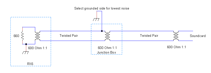
Tip 4: Check your grounding
You may have to ground and/or shield different parts of your cable run differently. Somewhat counter-intuitively, grounding one side of the first segment of my signal line helped to reduce hum by another 3 to 5dB. Go figure. Not a recommended way to do things, as it somewhat defeats the isolation you’re trying to achieve in the first place.
Tip 5: Large capacitance frightens Op-Amps
LArge capacitive loads frighten most op amps. If you take a look at the pF/foot(or meter) specifications for common coax or twisted pair cables, you will soon discover it doesn’t take a very long cable to produce a large capacitive load. As I stated in my analysis the RX-6, some op amps are better suited for driving these types of cable. However, you can help the situation by careful consideration of the cable you have on hand or are about to purchase. Try to minimize the C per unit length.
A Better Alternative: Optical Transfer
In order to optimize my reception as much as possible, I designed an optical transmission system to prevent domestic interference from entering the receiver via the transmission line and spoiling my low hum levels.
Given so little AC mains interference, I use only the receiver module itself which directly drives the optical transmitter. No additional filtering was needed. I detail the filter module I used with a wired connection at the end of this post.
Powering The Receiver
Connecting a mains powered DC supply to the receiver defeats the galvanic isolation you just worked so hard to achieve. My initial attempts at resolving this and powering my receiver used a solar panel with a basic current limiter and a sealed 12V gel-cell battery. The first few iterations of my receiver seemed to do fine with this arrangement. However, as the noise floor lowered and the system improved, I ran into a problem: hiss from the Sun. I removed the current limiter, double checked the panel to make sure that it was only a series of Si solar cells (and no active circuitry), and added filtering - but I was still unable to eliminate the hiss completely. The solar panel was fairly close to the receiver and antenna, so it could also have been capacitively coupled. Either way, I ended up dropping the solar panel altogether to eliminate the noise.
Currently, the RX-6 is powered via a 115AH deep cycle marine battery. A charge lasts for months, and the batteries have two important properties: cheap and simple.
Another option to consider is high-frequency (100kHz or higher) AC fed via twisted pair and isolation transformers.
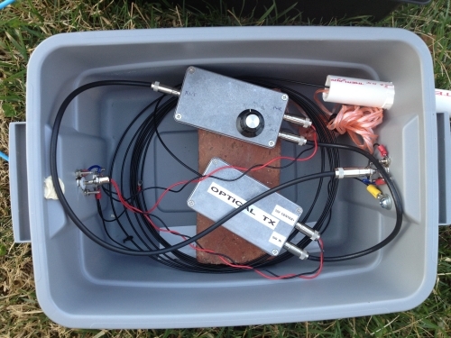
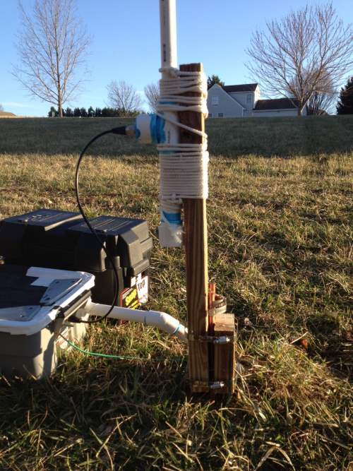
A Look At My System
Currently, I have the receiver and optical transmitter placed in a waterproof tub (which is quite handy for easy experimentation). A 50 meter run of optical cable (placed in 3/4 conduit for protection) is used to get the signal indoors. The optical receiver directly drives the input of the sound card.
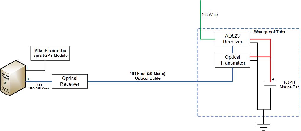
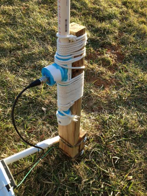
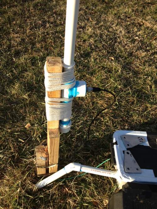
The whip antenna is approximately 10 feet tall, and made from 3/4" PVC pipe. Internally, it is 18ga hookup wire glued to the top cap, run through the length, and brought out through a “T” fitting and SO-239 connector. It is mounted to a piece of pressure treated lumber, which is in turn clamped to two ground rods. This arrangement provides some weight to the antenna, and seems to have eliminated the majority of noise from wind and rain.
Experience has shown that a somewhat flexible mounting method and whip tend to be less noisy than a firmly mounted one in strong wind. You want something that flops very gently from side to side in a strong wind - not something so flexible it flops around wildly, or so stiff it sings like a guitar string.
Here is a small gallery showing the external parts of the system:
System Performance
The noise performance of the receiver is very, very good, and well below the desired VLF signal. Coupled with the optical link, the entire system is extremely quiet, with excellent dynamic range. I am using the Behringer U-PHORIA UMC404HD to digitize the VLF signal. It it widely available, there is ALSA support, and the sample rate is relatively stable. It also has 4 channels, so in addition to the GPS timing signal and VLF E-Field input, I have room to add a set E-W and N-S magnetic receivers.
Logging & Processing The Signal
Once you get the signal indoors, there are quite a number things you can to do with it. Some suggestions:
- Catching Whistlers
- SID Monitoring
- VLF DXing
- Ionospheric Research
For processing the VLF signals, I continue to use Paul Nicholson’s vlfrx tool set. In my opinion, you just can’t beat the reliability and configurability of using a Linux-based system.
VLFRX Tool Set Notes
In the following description, I use the same notation Paul Nicholson uses in his documentation. Reviewing the section on streams and buffers first will help.
I currently have the vlfrx tool set installed on two linux systems. One ‘server’ currently connects to the USB sound card, and does data acquisition, GPS time stamping and signal calibration. The second does signal processing, streaming and storage, whistler (’event’) detection, and SID recording. Experience has shown that at higher sample rates, and with larger numbers of VLF stations being monitored by vtsid, it is difficult to run all of the components on a single machine (vtsid is one of the biggest consumers of CPU cycles, especially when measuring absolute phase.)
Startup Scritps
Here is the system that samples the VLF signal, performs sample rate correction, and GPS time stamps the signal:
#!/bin/bash

# Wait for 5 minutes for NTP to stabilize
/usr/bin/sleep 300

# Read VLF data from sound card. Timing is on channel 1; VLF is on
# channels 2,3 and 4.

# UMC404
/data/bin/vtcard -Bvv -L/data/log/vtcard_efield.log -A b=1536000,p=512 -r 192000 -d hw:1,0 -b32 -c4 @efield,15,i4

# Wait for @efield to be ready
/data/bin/vtwait -t @efield

# Start vttime
/data/bin/vttime -Bvv -L/data/log/vttime_efield.log -m ppsbase+,c=0.001216,w=auto -c1 @efield @timed

# Wait for @timed to be ready
/data/bin/vtwait -t @timed

# Start forwarding data to vlf02
/data/bin/vtcat -Bvv -L /data/log/vtcat-vlf02.log @timed:2 ++vlf02,9000,i2
The second system does all of the signal logging, event detection, and streaming:
#!/bin/bash

# Start collecting data from sound cards on other machines
/data/bin/vtcat -Bvv -L/data/log/vtcat_in.log ++9000 @calib,i2

# Wait for @calib to become available
/data/bin/vtwait -t @calib

# Start forwarding data to VLF03
#/data/bin/vtcat -Bvv -L /data/log/vtcat-vlf03.log @calib ++vlf03,9000,i2

# Create a filtered version of the stream
/data/bin/vtfilter -B -n 192000 -a th=6 -g6 @calib @filtered
/data/bin/vtwait -t @filtered

# Create a resampled version of the filtered stream to 32k
/data/bin/vtresample -B -r32000 @filtered @resampled
/data/bin/vtwait -t @resampled

# Create a resampled version of the raw stream to 32k
/data/bin/vtresample -B -r32000 @calib @resamp_raw
/data/bin/vtwait -t @resamp_raw

# Start recording resampled data to the long term data store
/data/bin/vtwrite -Bvv -G86400 -L /data/log/vtwrite_32k.log @resamp_raw /data/raw

# Start recording full bw data to the short term data store
/data/bin/vtwrite -Bvv -G3600 -L /data/log/vtwrite_192k.log @calib /data/raw-fb

# Start SID monitors
/data/bin/vtsid -Bvv -L/data/log/vtsid.log -c /data/sid/sid.conf @calib
/data/bin/vtsid -Bvv -L/data/log/vtsid2.log -c /data/sid/sid2.conf @calib

# Start EVENT monitor
/data/bin/vtfilter -B -n 192000 -a th=6 -h hp,f=200,poles=3 -h lp,f=8000,poles=3 -g2 @calib @event
/data/bin/vtwait -t @event
/data/bin/vtresample -B -r32000 @event @event32k
/data/bin/vtwait -t @event32k
/data/bin/vtevent -Bvv -L/data/log/vtevent.log -d /data/events @event32k

# Start remote stream to abelian.org
/data/bin/vtvorbis -Bvv -L /data/log/vtvorbis.log -eq0.8 -kn abelian.org,7835 @resampled

# Start local high-bandwidth stream (32k)
sleep 20
/usr/bin/icecast2 -c /etc/icecast2/icecast.xml &
sleep 15
/data/bin/local_stream2.sh &
Tip: Buffer sizes matter. Notice the “b=1536000,p=512” in the vtcard settings I use. This parameter increases the buffer used for passing samples from the sound card. To an extent, larger is better, as it helps vtcard cope with varying system loads. Its possible, however, to set it too high. vttime expects to ‘see’ a GPS timing pulse within a certain window of the sample buffer. If you make the buffer too large, that pulse can walk its way outside of that window and vttime will be unable to find it. In the end, you will probably need to play with the buffering a little to get a setup that works.
Filtering (If Needed)
If your environment needs some additioal filtering, here is a filter module design that I use in different experiments. The filter module is an adaptation of Charles Wenzels’ preamplifier stage of his “No Holds Barred” receiver system. I modified the notch filter to use the component values I normally use for a 60Hz notch, and changed the characteristics of the high pass filtering. Since I do not intend to use my e-field receiver to receive Schumann resonance peaks, I changed the filter to heavily suppress 0-60Hz, and have a more gradual rise after the 60Hz notch.
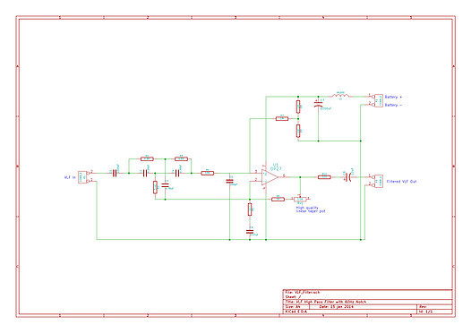
Click here for larger version.
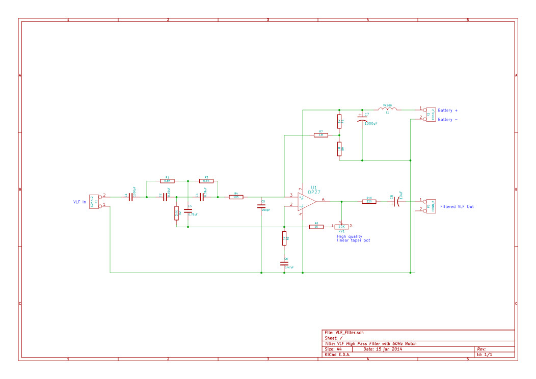
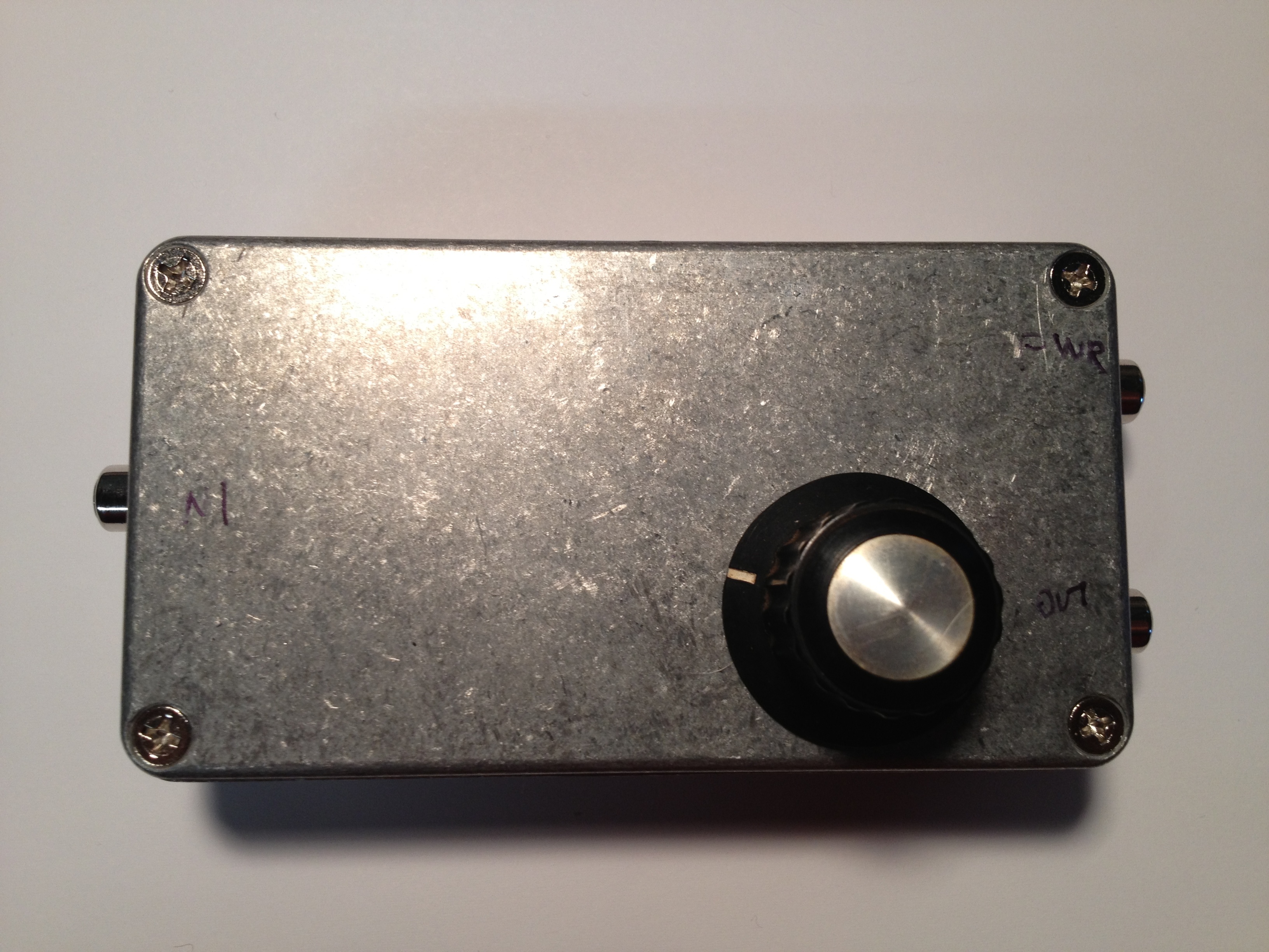
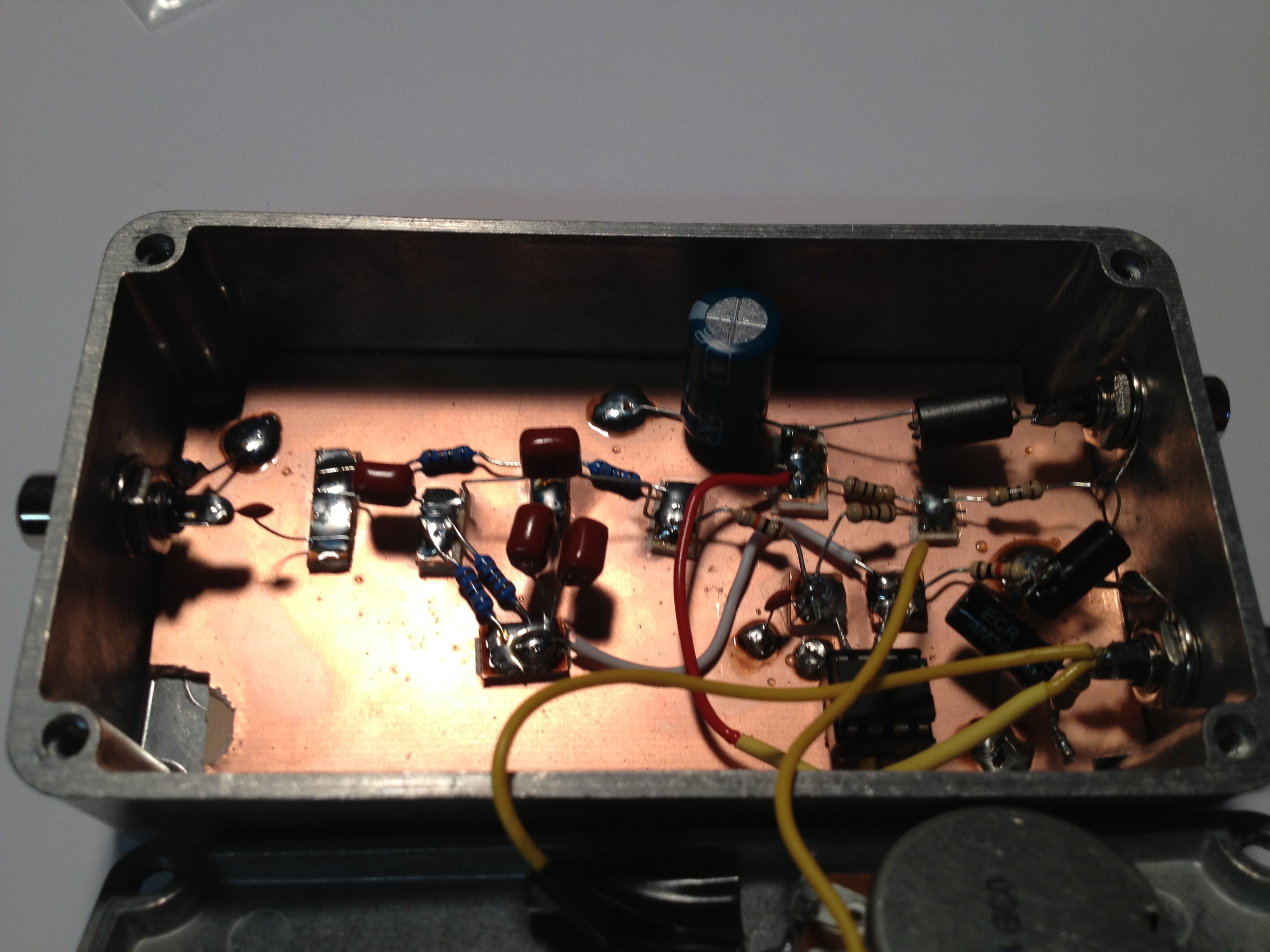
Here are a couple of photos showing the as-built filter. Again, I’ve used a high quality pot mounted on the case to ease experimentation and tuning in the field:
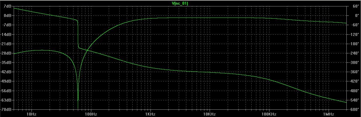
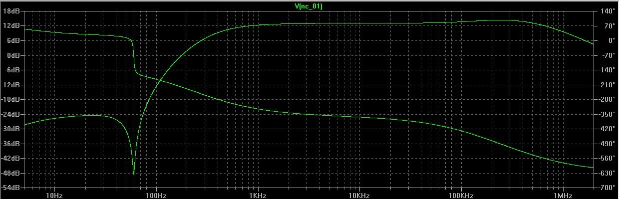
Filter Performance
Here are a the filter curves showing minimum (-1dB) and maximum (13dB) gain, respectively:
LTSpice Model
If you are interested in playing with this filter in LTSpice here is the LTSpice file. Note that the component values in the simulation are the measured values of the components that I used in the real world version.
The noise of the filter is lower than the VLF signal we are trying to process, and is quite similar to the noise curve of the receiver above.
Parting Toughts
I owe many thanks to Renato for writing his book in the first place, Paul Nicholson for his patient guidance, encouragement, and help as I experimented my way into operation, and to all of the members of Yahoo’s VLF_Group for providing years worth of good reading, analysis, and ideas. It is very, very appreciated.
Overall, I am pretty pleased with the results. The receiver is quite reliable, and sounds quite nice. I frequently listen to it in the background as I do other work.
I hope this page encourages you to take the plunge. You’ll be glad you did!
Handy VLF Links
- http://www.abelian.org/vlf/
- http://www.vlf.it/
- http://sidstation.loudet.org/stations-list-en.xhtml
- https://www.backyardastronomy.net/natural-radio-receiver